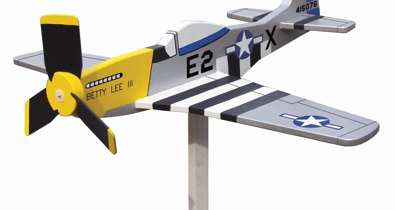
This model P-51 Mustang adds a whimsical touch to your yard or garden
By Paul Meisel
Of the various whirligig projects I have designed, the airplanes from World War II are my favorites. The P-51 Mustang was originally designed and built for the British air force. It first saw action in 1940. Later, the P-51 was used in the American air force.
The project in the photograph was painted to refl ect an American version. Many veterans feel it was one of the best all-around fighter airplanes of WWII. After the war, the P-51 remained in US service into the 1950s and served as a combat fighter in the Korean War. By the time the war ended in 1945, over 15,000 airplanes were built. About 150 remain airworthy today.
This P-51 Mustang whirligig is an easy project to make for your yard. You can follow my paint scheme or customize the whirligig with your own design. The body swivels to face into the wind, and the 3-blade propeller assembly spins in even the slightest breeze. I made the fuselage from ¾”-thick pine. The horizontal stabilizer and wing are both ½ “-thick exterior plywood. The propellers are cut from ⅛”-thick plywood. The drawings on the following pages should be enlarged 200% to make the whirligig to the original scale, using the stock listed in the materials list.
Step 1: Transfer the patterns to the stock. Enlarge the patterns and trace them onto the stock, using carbon paper. Flip the half-patterns over when tracing to make the full wing and stabilizer peices.
Step 2: Cut out the pieces. I use an Olson #456PGT blade to cut the ¾”-thick and ½”-thick stock. Cut the ½”-thick parts first. Then cut the profile of the fuselage. The slots in the fuselage must match the thickness of your plywood. Because plywood thicknesses vary, measure your plywood, and cut the slots in the fuselage to match.
Step 3: Cut three propellers from the ⅛”-thick plywood. I use an Olson #455PGT blade.
Step 4: Assemble the whirligig body. Insert the horizontal stabilizer and the wing in the slots in the fuselage. Glue them in place using water-resistant glue.
Step 5 (Click image gallery for a larger view): Assemble the propeller hub. Glue the propeller blades into the slots in the hub. Sand the surface of the plywood if the fit seems too tight. Slip a piece of scrap wood under the hub to raise it off the table, and secure each blade with two brads, one on each side of the hub. A brad pusher simplifies this task. Although not included in the parts kit, you may also wish to drive 5⁄8″ galvanized wire brads in to help secure the blades in the hub.
Step 6: Add the bushings. Insert one nylon-flanged bushing into the ¼”-diameter hole on each side of the propeller hub. Drill a 7⁄64″-diameter hole 1⅛”-deep in the front of the fuselage and attach the hub to the fuselage with a 2″ x #6 roundhead screw. Tighten the screw, but be sure the hub spins freely.
Step 7: Determine the balance point. Rest the project on your finger to determine the balance point. Mark ½” forward of the balance point, and drill a ¼”- diameter x 1¼”-deep hole in the bottom of the fuselage. The location of this hole may be different from that shown on the drawing.
Step 8: Add the fiberglass rod. Glue the ¼”-diameter fiberglass rod in the hole in the bottom of the fuselage. When you remove the whirligig from the post, you do not want the rod left protruding in case a child would fall on it.
Step 9: Paint the project. Use the reference photo and color recommendations on the patterns as guides, or do some research to find other paint schemes. Prime the project with a quality exterior-rated primer. Then paint the topcoats with exterior paint. Transfer the detail lines either freehand or by using graphite transfer paper. Then paint the accents. I use a black paint marker to outline the windows. Paint the stake green to blend with your lawn. You may wish to finish by brushing a coat of polyurethane over the final coat of paint. Caution: polyurethane may react chemically with some paints, especially the paint marker. If you apply polyurethane, test on a painted piece of scrap wood first.
Step 10: Display the project. It can be mounted on a deck railing, a fence post, or simply on a 2″ x 4″ or 4″ x 4″ wood post that has been pounded in the ground. Drill a 5⁄16″ hole 1¾ ” deep in the top of the post. Slip the 5⁄16″ nylon-flanged bushing in this hole. A 5⁄16″-diameter round bead or a ball bearing (not included in the parts kit) can be dropped into the hole to act as a bearing surface. After the project adjusts to the humidity, the hub may swell, so it may be necessary to adjust the screw after a few days.
Materials:
- ½” x 11″ x 30½ ” exterior plywood (horizontal stabilizer & wings)
- ¾ ” x 7½ ” x 24 5⁄8″ pine (fuselage)
- ¾ ” x 2 5⁄8″ x 3″ (propeller hub – optional, if ordering propeller package listed below)
- 1 ⁄8″ x 23⁄8″ x 12″ plywood (propellers – optional, if ordering propeller package)
- Single Engine, 3-Blade Propeller Hardware Parts Package (Meisel Part #2023SSW)*
- Graphite transfer paper (Meisel Part #9367)*
- 5⁄8″ x #18 gauge brads (Meisel Part #1609)*
- Sandpaper, 80 & 120 grits
- Exterior wood glue
- Stain blocking primer
- White exterior primer
- Exterior paint: white, blue, black, yellow, & silver
- Polyurethane (optional)
Tools:
- Olson #455PGT & #456PGT blades*
or blades of choice - Drill with 7⁄64″, ¼ “, and 5⁄16”-diameter bits
- Brad driver (Meisel Part #7081, optional)*
- Slotted screwdriver
- Paint brushes
*SPECIAL SOURCES:
A propeller hardware parts kit, including all bushings and shafts, a pre-cut hub and 1⁄8″ exterior birch plywood for propellers, is available for $5.99 (order part #2023SSW).
Other available materials listed above: #9367 Graphite Transfer Paper $14.00 for 12 sheets, #1609 5⁄8″ x #18 gauge wire brads, $1.59/1.75oz box, plus S&H from: Meisel Hardware Specialties, P.O. Box 70, Mound, MN 55364, 800-441- 9870, www.meiselwoodhobby.com
Attachments
Nose and Cockpit Pattern
Tail Pattern